A custom controller board for WS2812-style LEDs
Design Objectives
I wanted to design an LED controller that had the following features:
- Processing power to run WLED firmware and drive several thousand pixels at 15 fps minimum.
- Hardware for wired ethernet networking, to support low-latency synchronization to music or other lights.
- On-board power conversion to safely draw power from 12V power supplies and output 5V logic as expected by the LED strips.
- Low cost per unit, less than $20 each assembled.
Controller Design
I explored a few different control board options, including some off-the-shelf solutions like the ESPixelStick and Raspberry Pi-based controllers. No option had everything I wanted, however, so I decided to produce my own board.
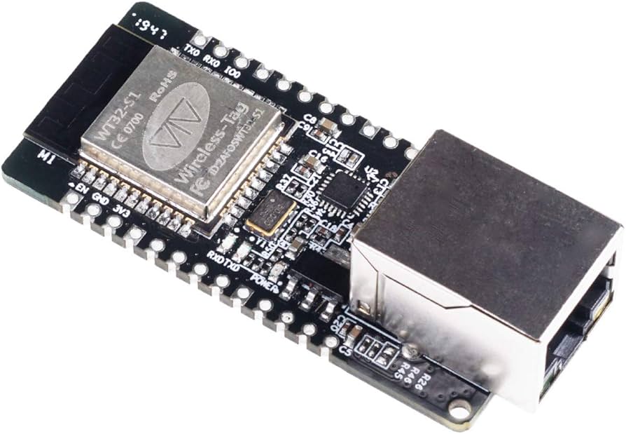
I did, however, discover the ESP32-ETH01 development board. This board already had Ethernet networking built in, saving me the difficulty and cost of creating my own networking solution. At ~$10 per board, they were not quite as cheap as I would prefer, but the offered a nice off-the-shelf crutch that could be replaced with a custom part in the future. As an added bonus, the WLED project already had a build for this board, saving hours of firmware development down the line.
Prototype V1
I designed a master schematic for the project in KiCad. The original design was extremely simple, with just a level shifter IC for to convert the 3.3V logic of the ESP to the 5V logic of the LED strands. and a few headers to connect the output leads and UART. In the initial prototype, I used the much cheaper ESP32-WROOM-32 board, which lacks the RJ45 jack but costs less than $3.
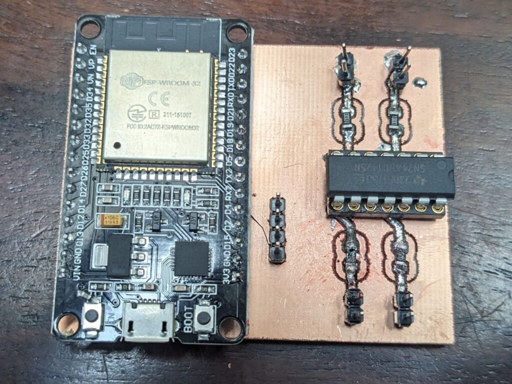
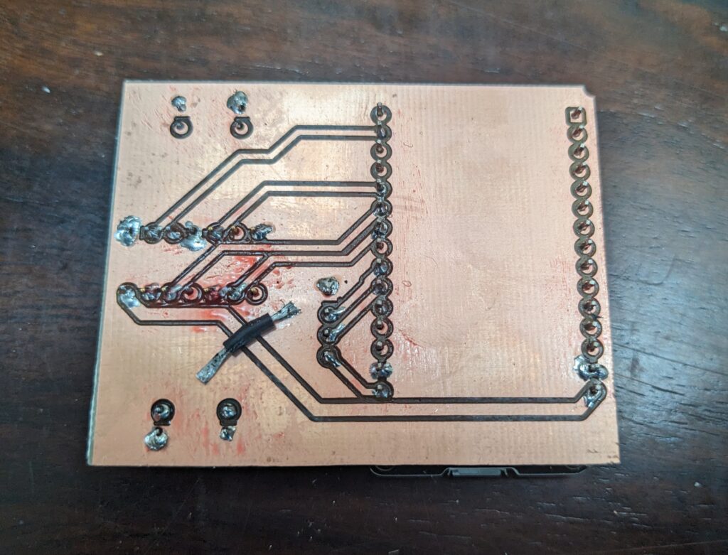
I saw this project as an opportunity to try machining my own PCBs from raw copper-clad FR4 stock with my desktop CNC mill. While I am very happy with quality the eventual results, producing a usable board took a long time and careful tending to the machine. The final product also did not have solder mask, silkscreen, or plated through-holes, making working with these boards much more difficult than with a commercially produced board. I decided to make the next iteration with a commercial board house.
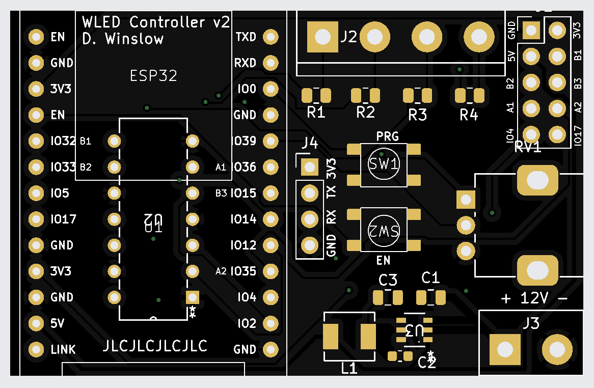
V2 Board
The revised V2 schematic was much more ambitious. Not only did it incorporate the more complex ETH01 board, but it also represented my first attempt at a switching power supply. I also included a small pot knob connected to a GPIO for WLED to use as a multipurpose input and a header to break out pins for extra buttons, encoders, or capacitive sensors for control in a variety of use cases.
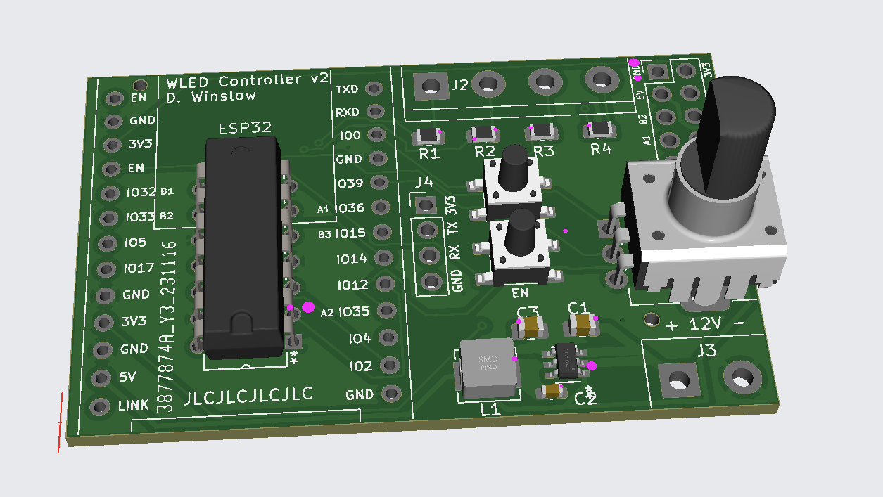
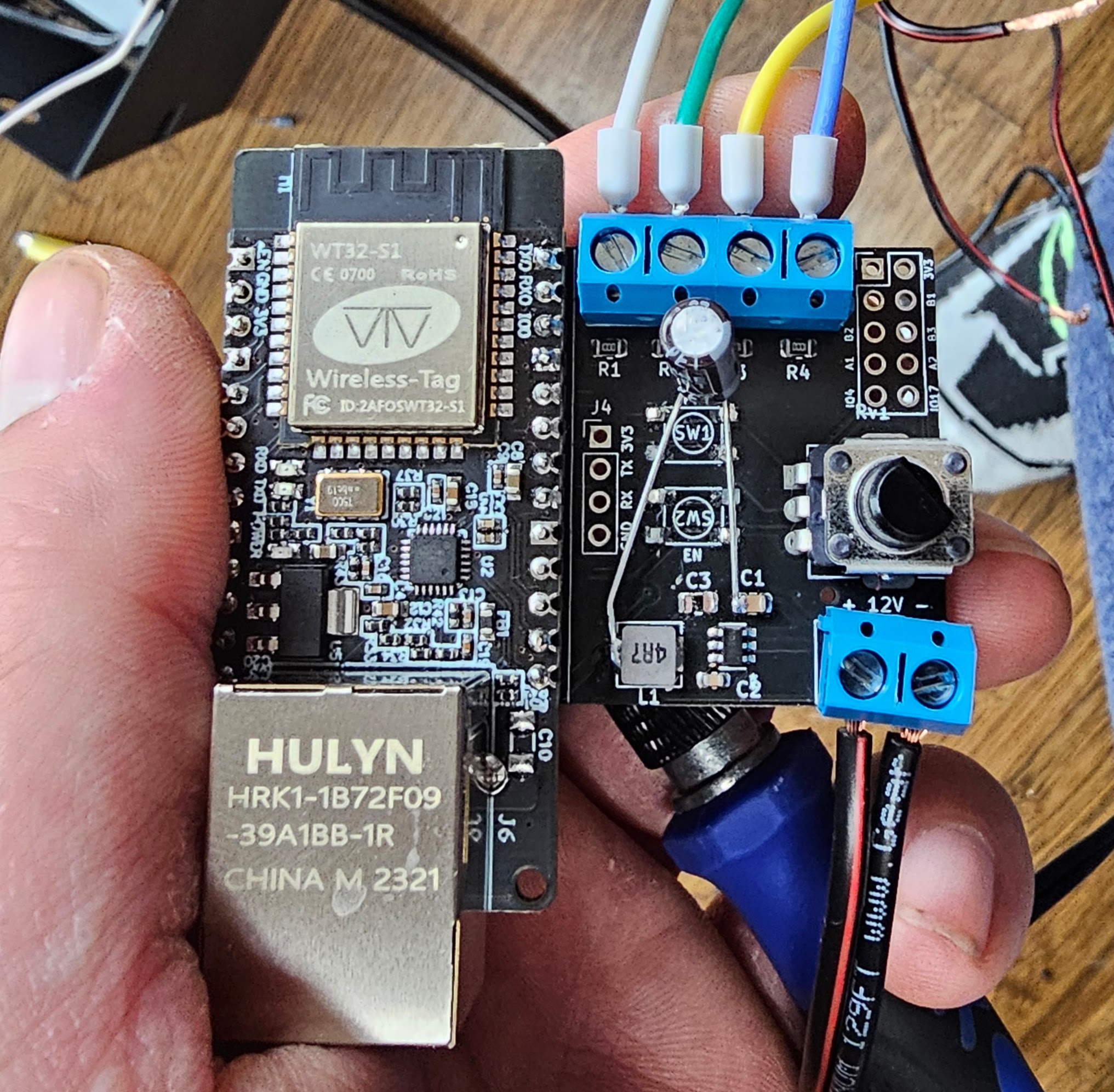
To save space, I placed the level shifter IC under the ETH01 board. This required some creative routing, but eventually worked without requiring a multi-layer board, keeping the cost per unit low. Without reflow equipment in my home workshop, I opted to have the board partially assembled.
V3 and beyond
As much of an improvement as V2 is over V1, it still is not perfect. A small routing error in the switching power supply requires a simple rework on each board, while an undocumented issue with the ETH01 board requires an extra RC delay on its reset pin. Additionally, an error with my footprint for the momentary switches causes them to be held permanently to ground, rendering them inoperable. Both of these issues can be simply solved with the next iteration of the board, but until then, the 5 boards I have are perfectly serviceable. Long term, it would be nice to remove the ETH01 as a dependency and build the board directly with an ESP32 module and an ethernet manager IC. A status LED or two would also add another level of usability to the board for very little extra BOM cost.